The practical answer to how to document software architecture is a small set of pictures in git: a context diagram, one sequence for a request that matters, and one data model. Three files. Updated in the same pull request as the code they describe. Everything else is optional until a question repeats itself in review. This page is that set, drawn with Mermaid so the diff is a few lines of text. The zoom levels are covered in how to draw a C4 diagram. Sequences have their own walkthrough in the sequence tutorial. Tables and keys are in ER diagrams from SQL.
You do not need a poster that shows every service, every queue, and every region. That poster is out of date before the meeting ends. A short set that stays true beats a complete set that is fiction.
The set, and the question each picture owns
Give each diagram one job so they do not grow into each other.
| Picture | Job | Open this when |
|---|---|---|
| Context | Who uses the system, and which outside systems it needs | A new person joins, or security asks where data goes |
| Sequence | One runtime path, step by step | Someone asks what happens when the user clicks |
| Data model | The nouns you store, and how they point at each other | A migration changes a relationship |
A flowchart of services is a fourth picture you add when the team keeps redrawing boxes in a design doc. A cloud icon diagram is a fifth, for infrastructure reviews. They are allowed. They are not the starting set. The architecture diagram syntax, with groups and icons, is one way to draw that fifth picture. A flowchart is another. C4 containers are another. Pick the one your readers already know how to read.
Context, kept boring
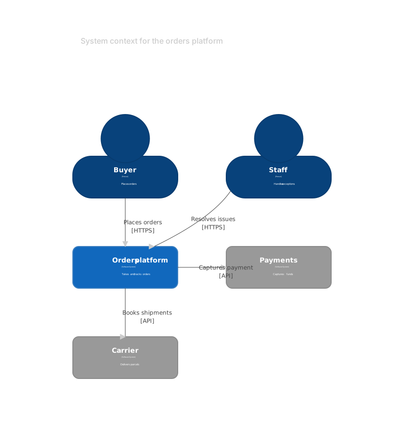
The context diagram names the system once, the people who use it, and the external systems you would mention in a status update. How to choose the boxes is the C4 guide. Here is the shape, small enough to maintain:
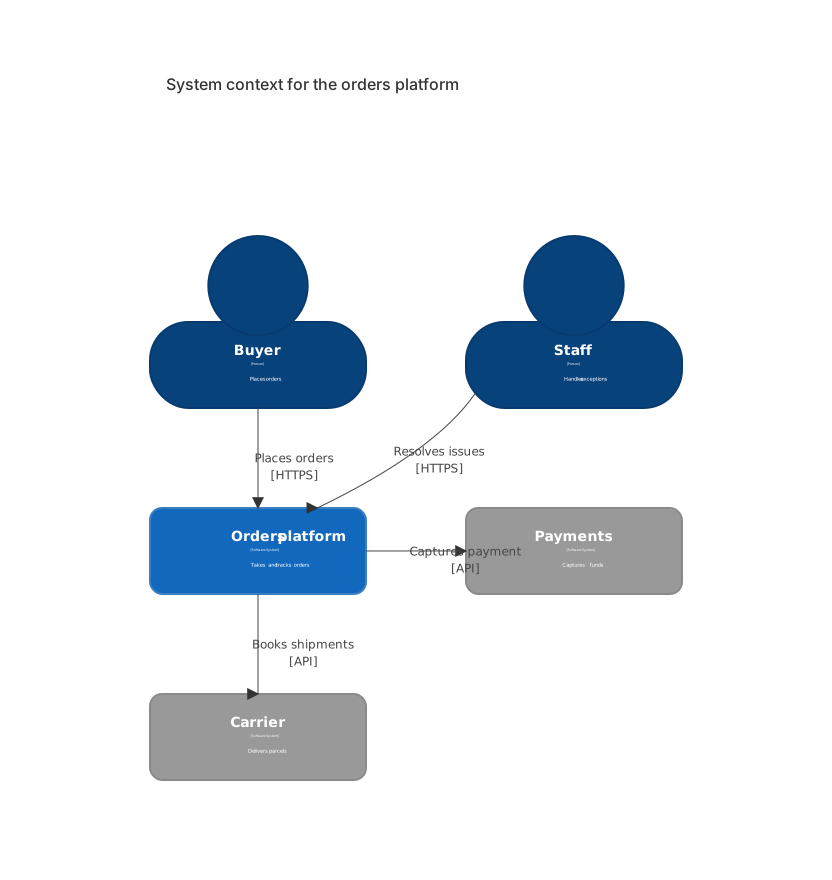
C4Context
  title System context for the orders platform
  Person(buyer, "Buyer", "Places orders")
  Person(staff, "Staff", "Handles exceptions")
  System(orders, "Orders platform", "Takes and tracks orders")
  System_Ext(pay, "Payments", "Captures funds")
  System_Ext(ship, "Carrier", "Delivers parcels")
  Rel(buyer, orders, "Places orders", "HTTPS")
  Rel(staff, orders, "Resolves issues", "HTTPS")
  Rel(orders, pay, "Captures payment", "API")
Rel(orders, ship, "Books shipments", "API")If you cannot explain a box without opening an IDE, it does not belong on this picture. The database is inside "Orders platform." The email vendor can be added the day a reviewer asks which messages leave the building. Until then it is a detail of the sequence that sends mail.
Put this file at docs/architecture/context.md. Link it from the service README in the first screen, not in a footer nobody opens.
One sequence, for one path
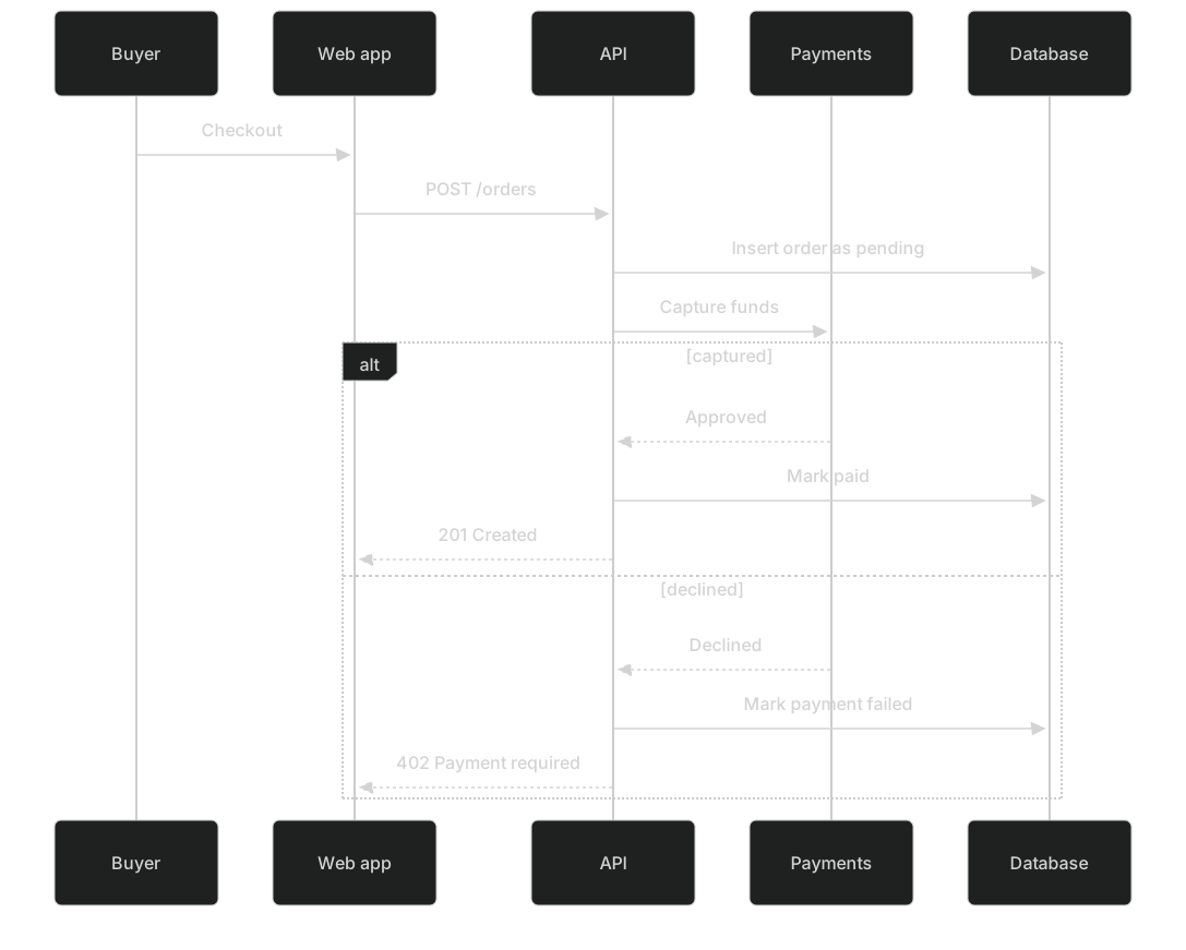
Pick the path that pages people. For an orders platform that is "place an order," not "update a profile theme." A sequence shows participants in time order. The sequence tutorial covers loops, alt blocks, and notes. The architecture set needs one happy path and the one failure you actually handle.
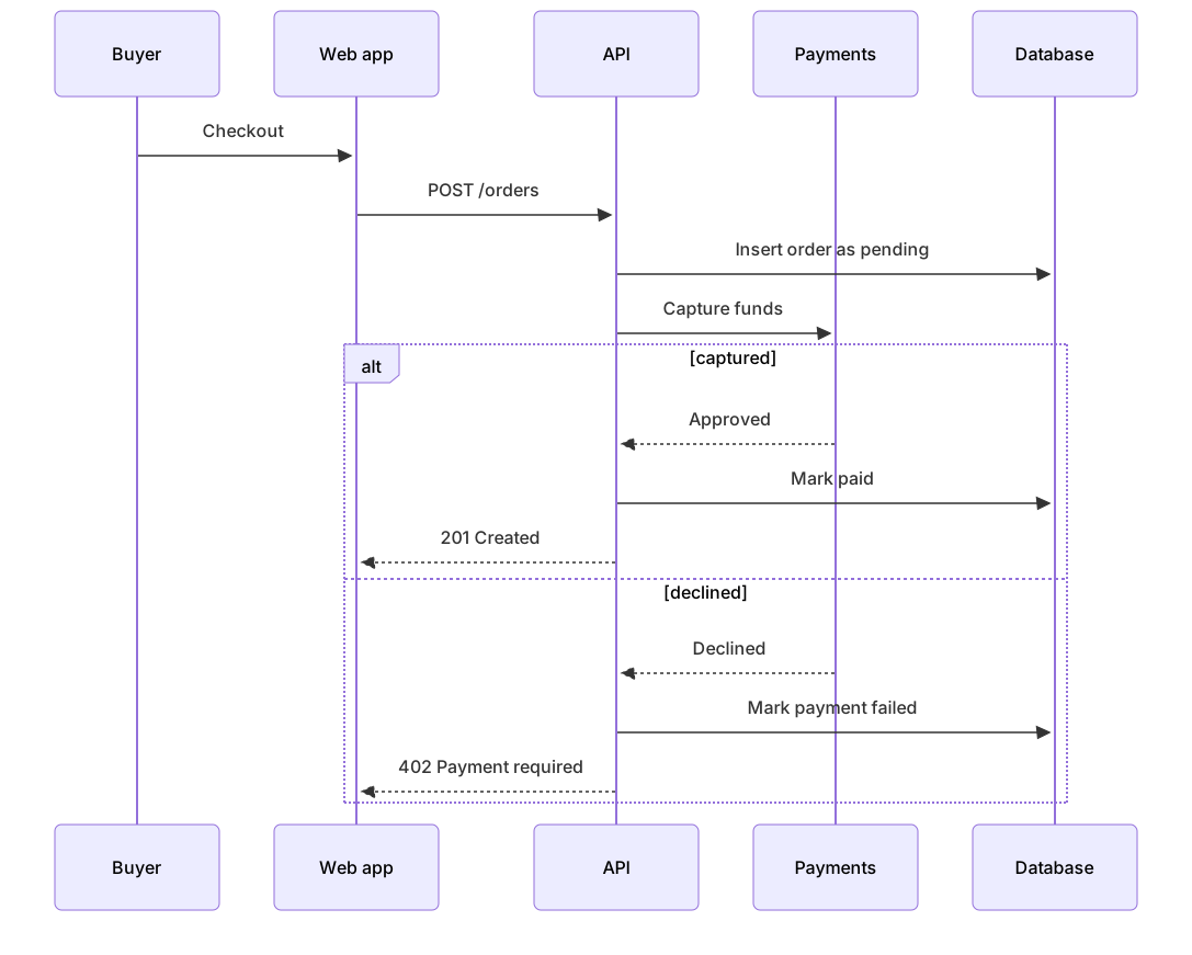
sequenceDiagram
  participant B as Buyer
  participant W as Web app
  participant A as API
  participant P as Payments
  participant D as Database
  B->>W: Checkout
  W->>A: POST /orders
  A->>D: Insert order as pending
  A->>P: Capture funds
  alt captured
    P-->>A: Approved
    A->>D: Mark paid
    A-->>W: 201 Created
  else declined
    P-->>A: Declined
    A->>D: Mark payment failed
    A-->>W: 402 Payment required
endParticipants are the containers from the next level down, or the obvious processes if you have not drawn containers yet. Do not invent a "manager" participant that has no process. If the web app never talks to payments, do not draw that arrow here just because the context diagram has a payments box. The context says the platform talks to payments. The sequence says which process does it.
One sequence per file, named for the path: docs/architecture/place-order.md. A second path, such as "refund," gets another file when refunds are a real support burden. Stuffing five paths into one sequence makes an unreadable ladder. Link the files from the context page so a reader can see the index.
Keep the messages as real calls. POST /orders is something a log contains. Process checkout saga is a mood. When the route changes, the sequence changes in that pull request. That is the maintenance cost, and it is small because you only promised one path.
One data model
The data model is the nouns, the keys, and the relationships the code assumes. Generate the first draft from SQL if you already have tables. The ER guide shows that direction. Then delete tables that are not part of the story this page tells. Audit columns and job-lock tables can live in the schema and stay off the architecture picture.
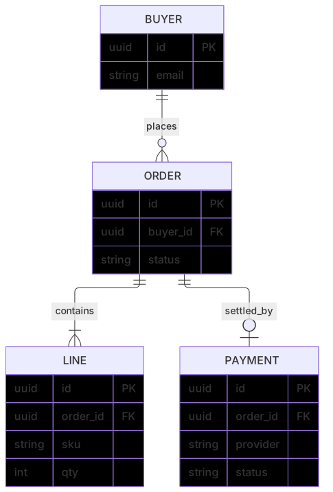
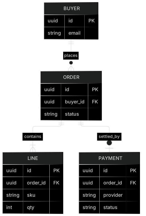
erDiagram
  BUYER ||--o{ ORDER : places
  ORDER ||--|{ LINE : contains
  ORDER ||--o| PAYMENT : settled_by
  BUYER {
    uuid id PK
    string email
  }
  ORDER {
    uuid id PK
    uuid buyer_id FK
    string status
  }
  LINE {
    uuid id PK
    uuid order_id FK
    string sku
    int qty
  }
  PAYMENT {
    uuid id PK
    uuid order_id FK
    string provider
    string status
}status on ORDER and PAYMENT is a hint that a state diagram exists, or should. Do not draw the states inside the ER diagram. Link the state machine next to the column. The ER picture says the column exists. The state picture says which values are legal.
Store it at docs/architecture/data-model.md. When a migration adds a table that changes the story, update the fence in the migration's pull request. A follow-up ticket called "update the diagram" will not get done, and then the diagram becomes evidence of a system you no longer run.
Services, when the boxes are the question
Sometimes the argument is the split between services, not the context and not one request. A flowchart with a gateway, a few services, and their databases is enough. The microservices template is a fuller version of this sketch. Use it when you are documenting that shape. Fold it back into the three-file set when the split is stable and the questions move on to requests and data.
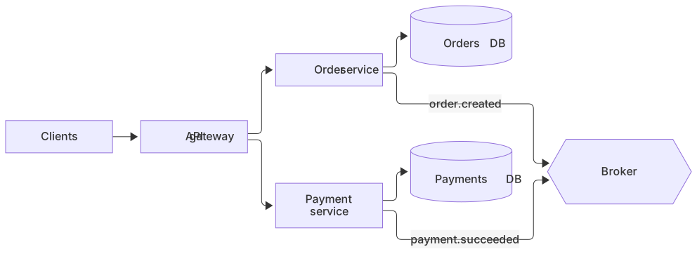
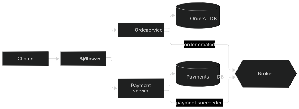
flowchart LR
  Client[Clients] --> GW[API gateway]
  GW --> O[Order service]
  GW --> P[Payment service]
  O --> ODB[(Orders DB)]
  P --> PDB[(Payments DB)]
  O -- order.created --> MQ{{Broker}}
P -- payment.succeeded --> MQEach service owns its database. The arrow to the broker is a fact you can check in the code. If payment calls orders over HTTP as well, draw that too, or the picture will be used to claim a decoupling you do not have. This is the diagram that lies by omission more than the others, because a missing arrow looks like a clean architecture.
An icon diagram can show the same runtime with clouds and disks. Reach for it when the audience is an infrastructure review and the icons match the console they use. Reach for C4 containers when the audience wants technology labels and a boundary. Reach for this flowchart when you want the smallest picture that still shows who owns which database. Three options, one question. The file in git should contain the option you chose, plus a sentence that says why.
How the files stay true
- Put the three files under
docs/architecture/in the repo that owns the system. A wiki page that nobody's CI checks will drift. - In the pull request template, add a line: "If this change alters a public call, a stored relationship, or an external system, update the architecture docs."
- Review the diff of the fence the way you review the diff of a test. A deleted arrow needs a reason in the description.
- Preview in the editor before you merge, so a missing quote does not blank the page on GitHub. The syntax error guide is there when the line number is all the host gives you.
- Download a PNG for a slide deck the morning you need it. Free PNG is 1× with a watermark, Starter goes to 4×, and Pro goes to 8×. SVG is on Pro. Do not commit the image as the source. The fence is the source.
A monorepo can keep one docs/architecture at the root. A multi-repo system should keep the context diagram in the repo that owns the user-facing app, and link out to the other repos for their sequences. Duplicating the context in every repo guarantees they will disagree. Pick an owner.
Names should match the code. If the service is orders-api in the deploy config, the participant is orders-api, or the prose says "API (orders-api)." Cute names ("the brain," "the vault") feel friendly and fail search. On-call will grep the docs for the name in the alert. Make the grep hit.
What to add later, and what to refuse
Add a diagram when the same question shows up in two reviews and the existing three pictures do not answer it. A deploy diagram after a region failover. A second sequence after refunds confuse support. A state diagram after status grows a value nobody documented.
Refuse the all-in-one diagram. It tries to be context, sequence, and schema at once, and it answers none of them. Refuse a generated dump of every class. That is an index, and the repo is a better index. Refuse a screenshot of a whiteboard as the only copy. Take the photo, then write the three fences while the pen is still dry. The photo can sit in the pull request for a week. It should not be the thing you open next quarter.
If you are starting from a blank repo, write the context from memory first. You will forget an external system, and the act of writing will surface it. Then trace one real request in the logs and turn those lines into the sequence. Then paste the tables that request touches into an ER diagram. That order matches how you learn the system, so the docs match the learning.
The AI diagram generator can draft any of the three from a paragraph. Use it for the draft. Then delete participants you cannot find in the repo, and add the failure branch the model skipped. A polished diagram of a system you do not run is a liability, because it reads as official.
Decisions live next to the pictures
A diagram shows what is true. An architecture decision record says why a different shape was rejected. Keep them in docs/architecture/decisions/ and link the record from the diagram that would otherwise look arbitrary. The sequence that calls payments synchronously looks naive until the note points at the decision: "we tried a queue here and refunds raced." Two sentences and a link. Do not paste the whole decision into the diagram as a note. Notes on arrows should stay shorter than the arrow label.
Number the records. 0001-sync-capture.md is enough. The diagram does not need to repeat the number in a box. When you reverse a decision, update the diagram in the same commit as the new record, and mark the old record superseded. A folder of decisions that contradicts context.md is how new hires learn the wrong system with confidence.
Write the decision after the diagram exists, not before. The picture will show you which alternative you are actually rejecting. Teams that write a long decision first often describe a system they never draw, and the two documents diverge on day one.
A review you can finish in ten minutes
Read the context and name every external system out loud. If one of them was retired, delete the box today. Read the sequence and find the handler for POST /orders. If the handler also writes an audit table the ER diagram hides, either add the table or decide the audit table is out of scope and say so under the picture. Read the ER diagram and confirm the foreign keys. A relationship drawn as one-to-many that the database does not enforce is a bug in one of the two artifacts. Fix the one that is wrong, not the one that is prettier.
Onboarding is the test. A new engineer should open docs/architecture/context.md, name the external systems, follow one link to the place-order sequence, and find the tables that sequence writes. If they have to ask where the docs are, the README link is missing. If they have to ask which of twelve diagrams is current, you have a gallery, and the gallery should shrink back to the three files plus the decisions folder.
That is how to document software architecture without standing up a documentation program. Three pictures, in git, owned by the pull requests that change the system. Add a fourth when a real question demands it. Link the C4 guide, the sequence tutorial, and the ER guide from the index page so the syntax never has to be rediscovered in a hurry. When a diagram fails to render on the host you ship to, fix the fence before you add another picture. A blank panel in the README teaches people to ignore the whole folder.
Frequently asked questions
Which Mermaid diagram should I use for architecture?
Use a C4 context diagram for the audience outside the team, a flowchart or architecture diagram for request paths, a sequence diagram for one important interaction, and an ER diagram for the data.
How many diagrams do I need?
Start with three: context, one runtime flow, and the data model. Add more only when a question keeps coming up in review.
Where should the diagrams live?
Next to the code, in the repo's docs or README, so a pull request can update the picture in the same change as the system.